Menu
Control panel
This computer-connected control panel allows me to assign a physical switch to repeatedly used actions buried in menus or hidden in-between myriad desktop icons. I intend to use it every day to control VPN connections, remote drive mounting and programs I use everyday. To not limit it to controlling single computer, I decided to use wifi-enabled module and MQTT broker to relay the controls. This way I can connect it to multiple targets, even to the "smart" light control at home.Project log
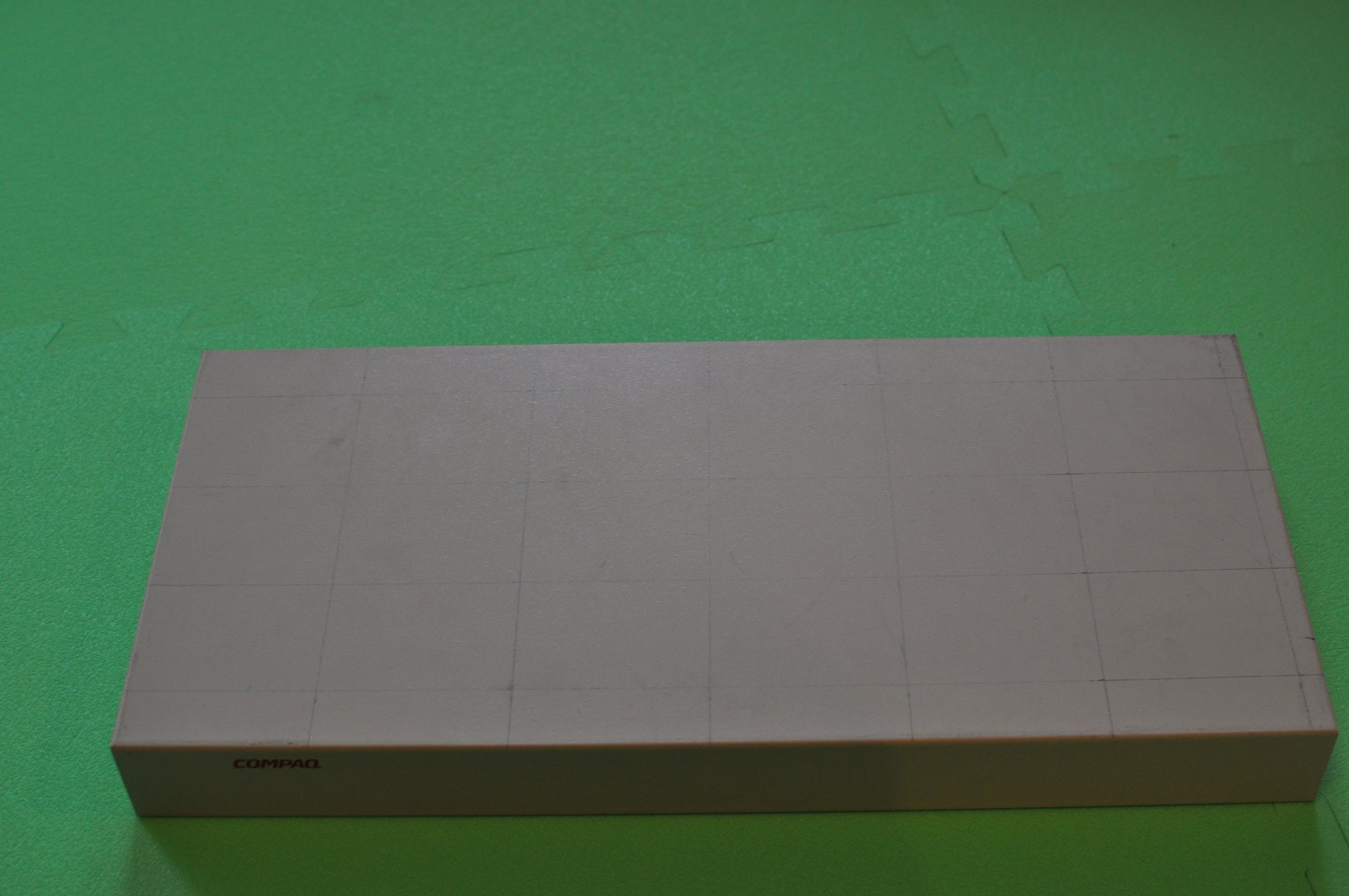
2020-10-09: Switches from china finally came in mail, so it's time to start working on the project. First I started looking for an enclosure for the panel.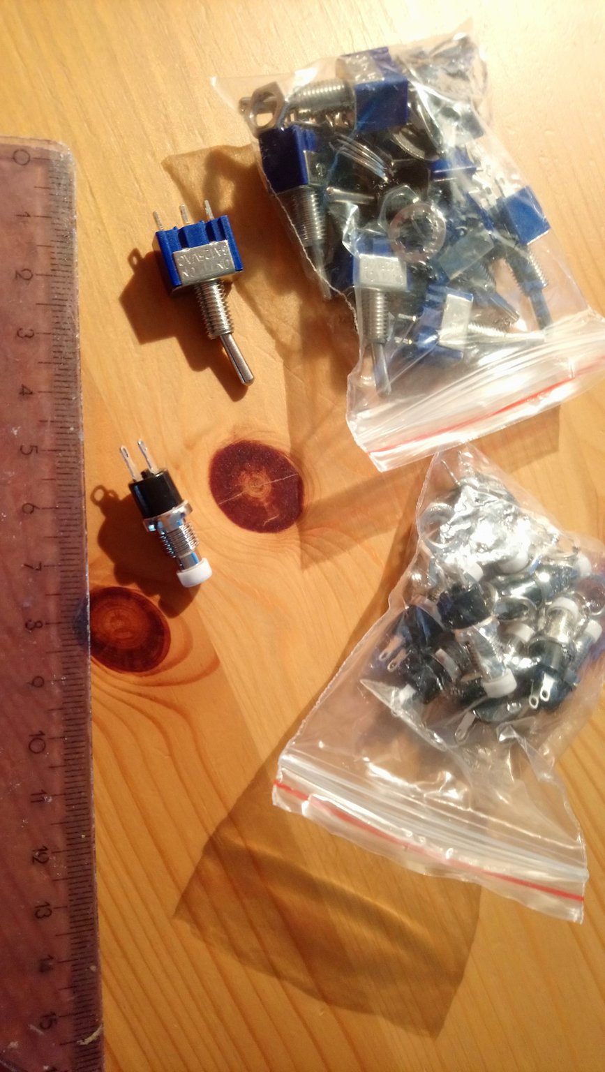 Switches
2020-10-10: Soon enough I discovered an old KVM switch with a case of suitable dimensions I had laying around, so I decided to reuse it's case for this project. The disassembly yielded some screws, nice power supply, mainboard and most importantly the case.
Then some calculations about the dimensions were made and I decided to go with 6x4 layout. First column will be fitted with push buttons, remaining columns with lever switches. There will be a little indicator light on the left of each switch.
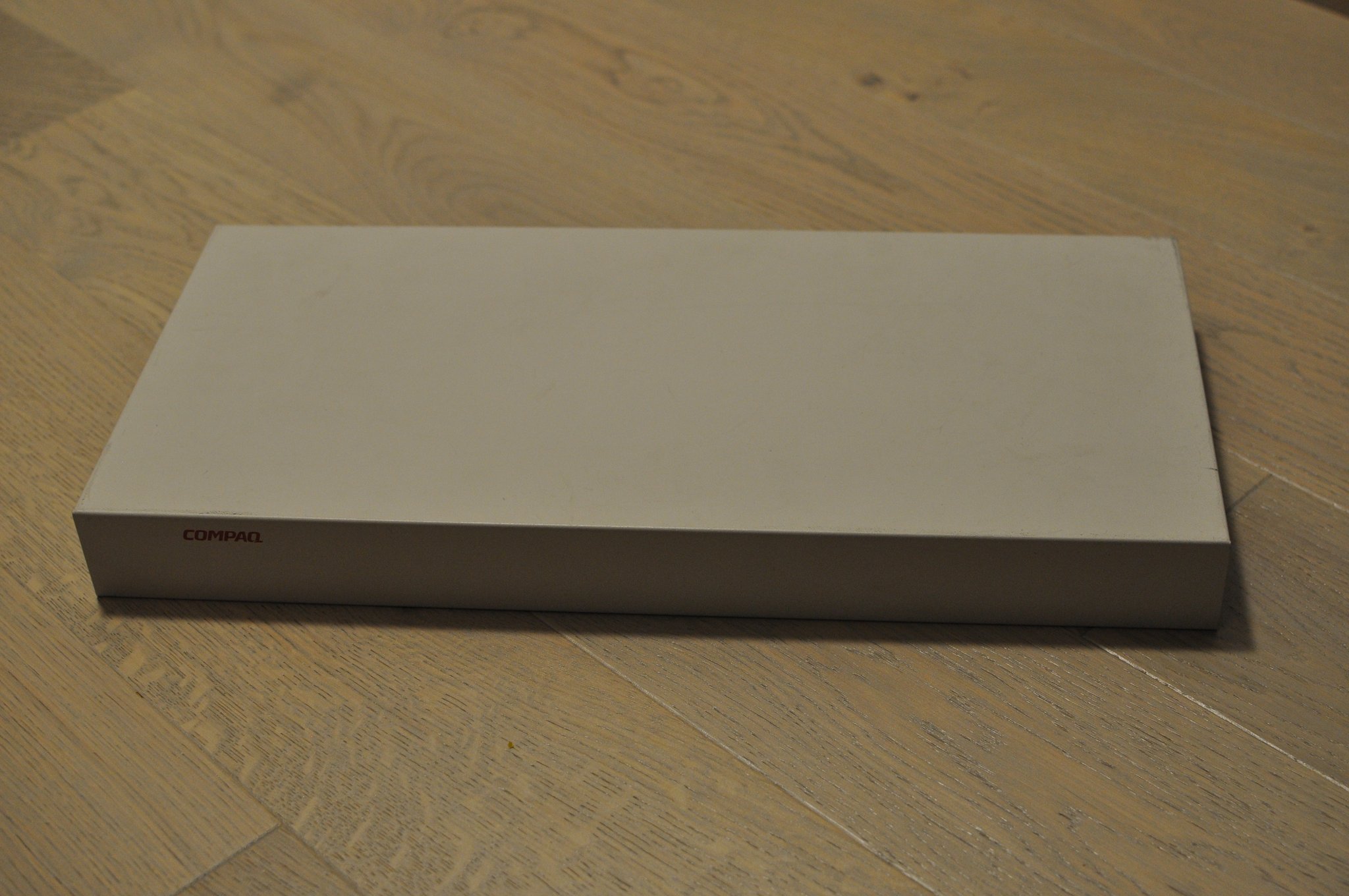 KVM front
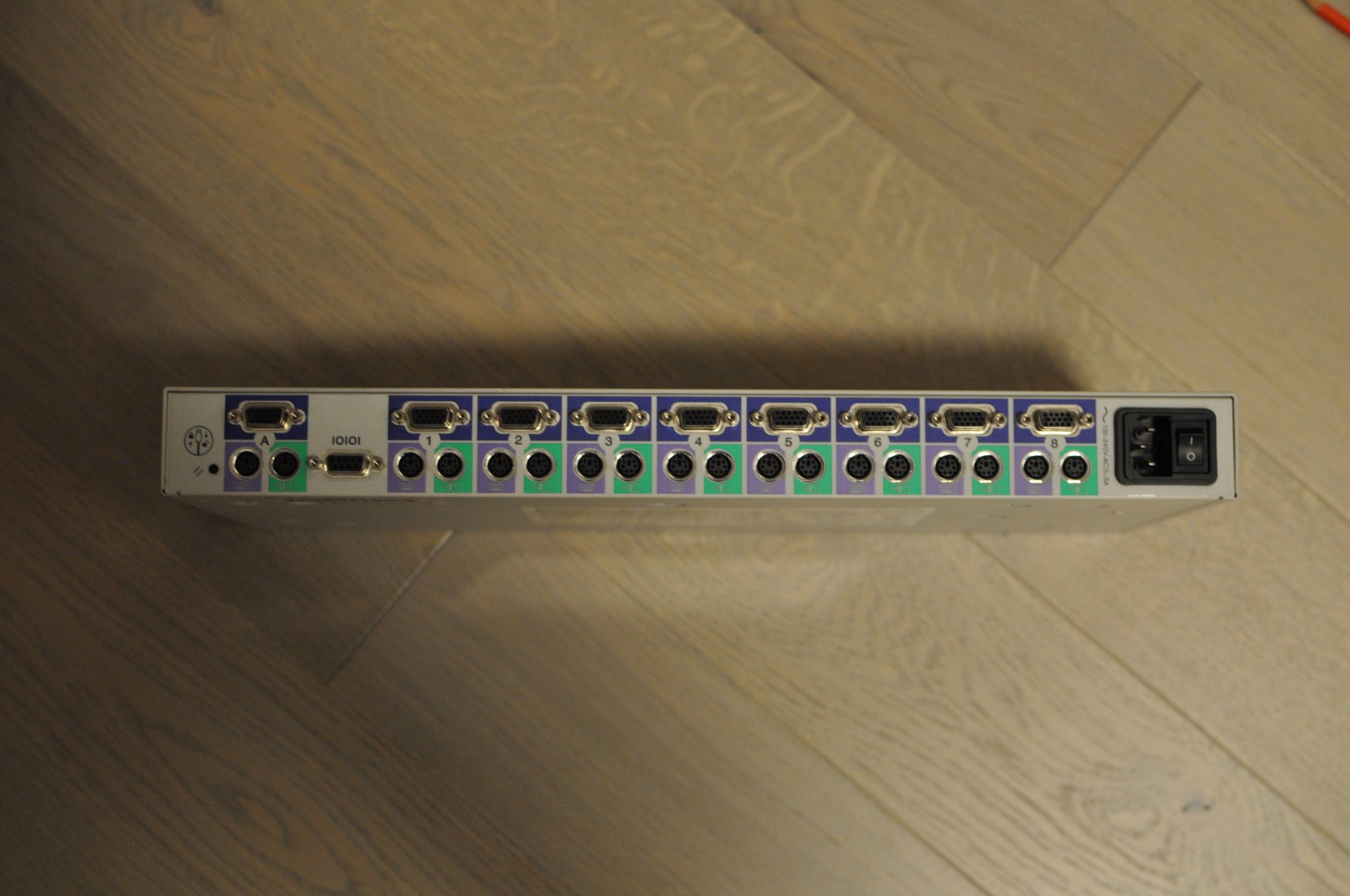 KVM back
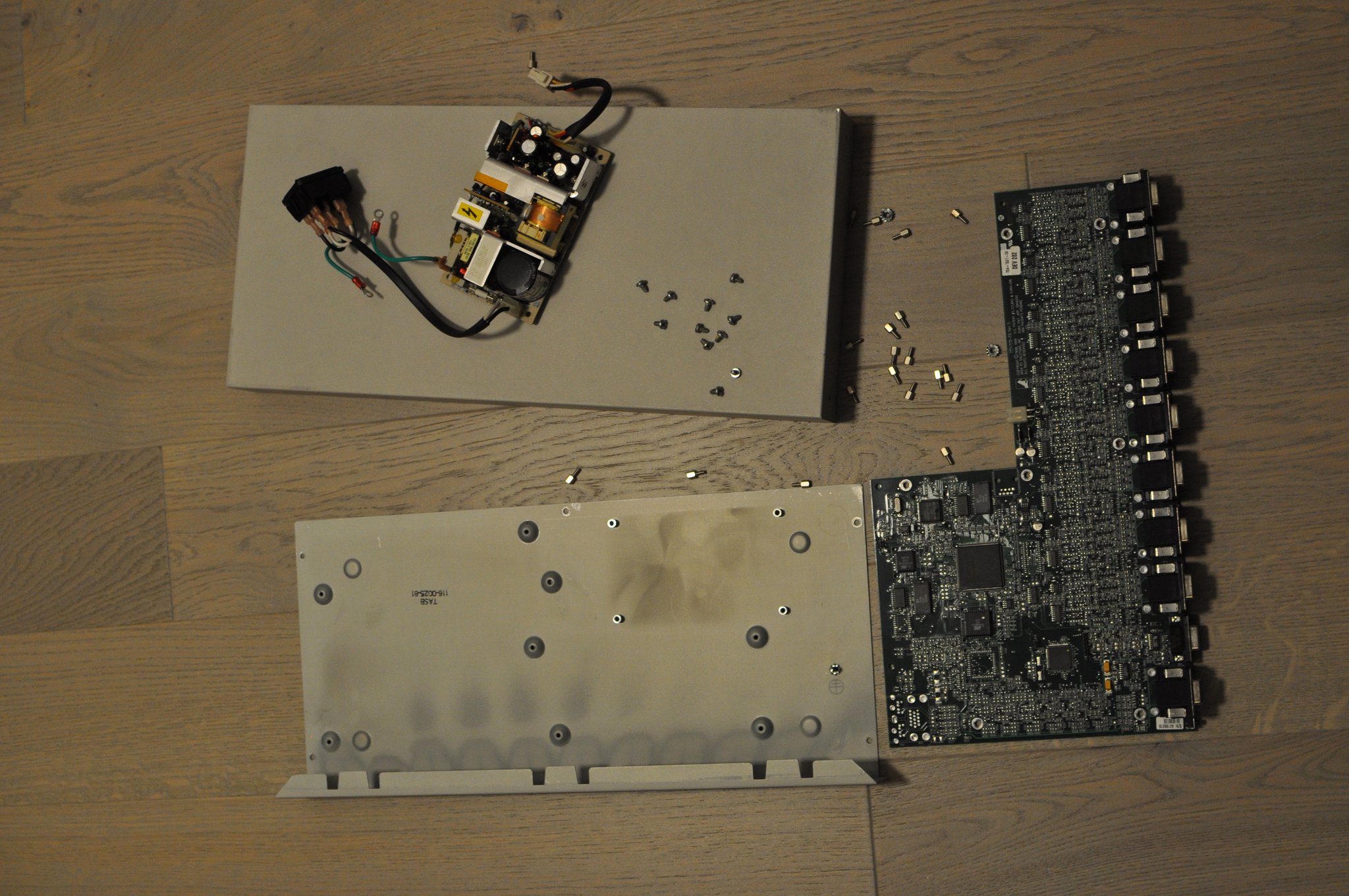 KVM disassembly
 layout
2020-10-11: The layout was drawn in pencil on the case and I pre-drilled the holes with a small diameter drill, then I drilled small holes for indicators and large holes for the switches, starting on the outside. Don't tell anyone I fucked up the second column and drilled a large hole instead of a small one. I finished the holes with larger diameter drill to remove the chips and rough edges. After cleaning the pencil traces the panel is ready for mounting the switches. Here I got a helping hand from my little girl. After tightening the nuts the switches are ready for soldering.
 Layout drawn in pencil
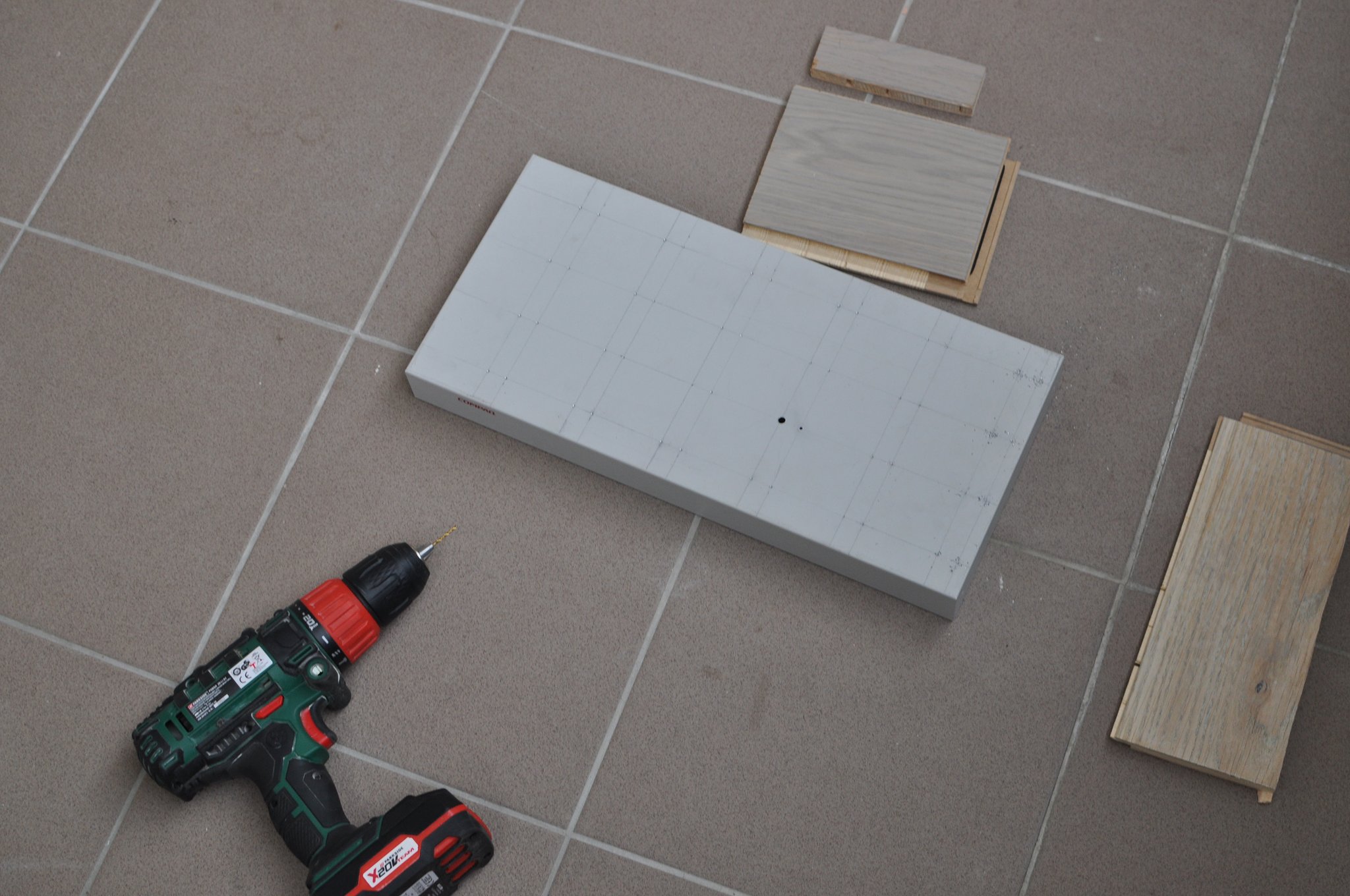 Pre-drilling the holes
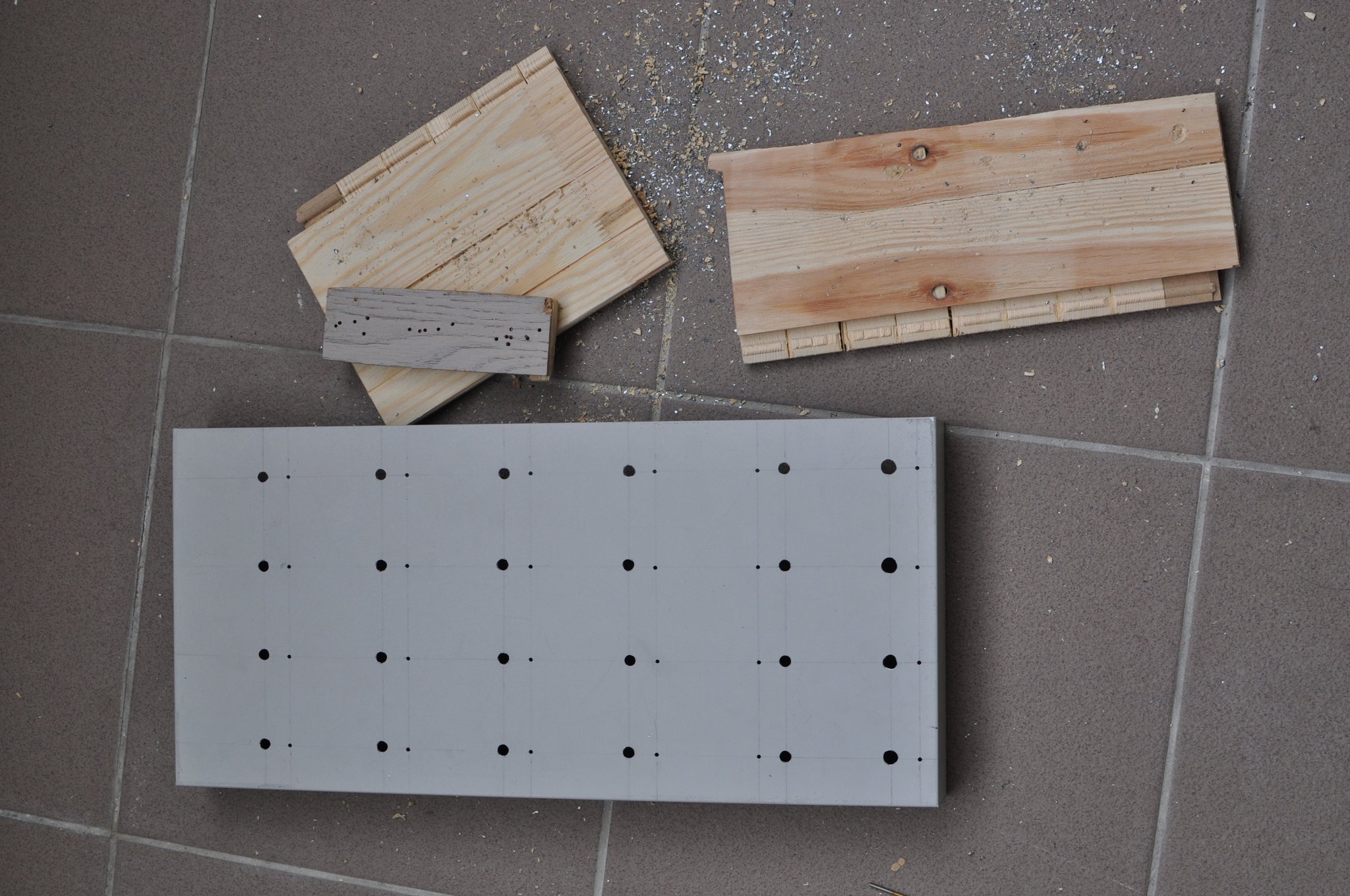 All holes drilled
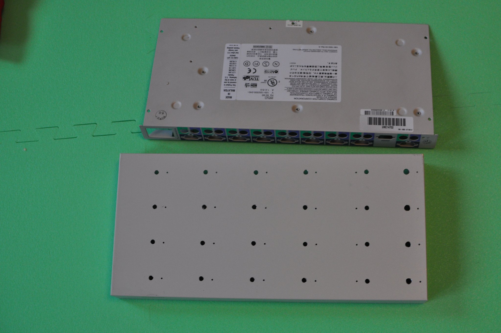 Cleaned pencil traces
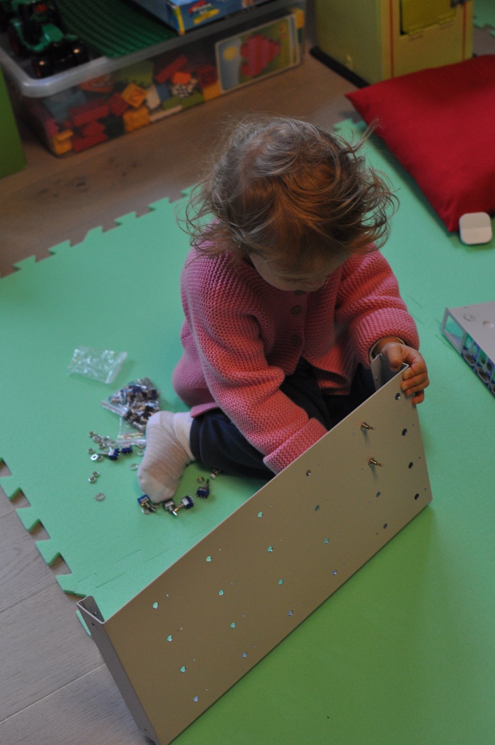 Mounting the switches
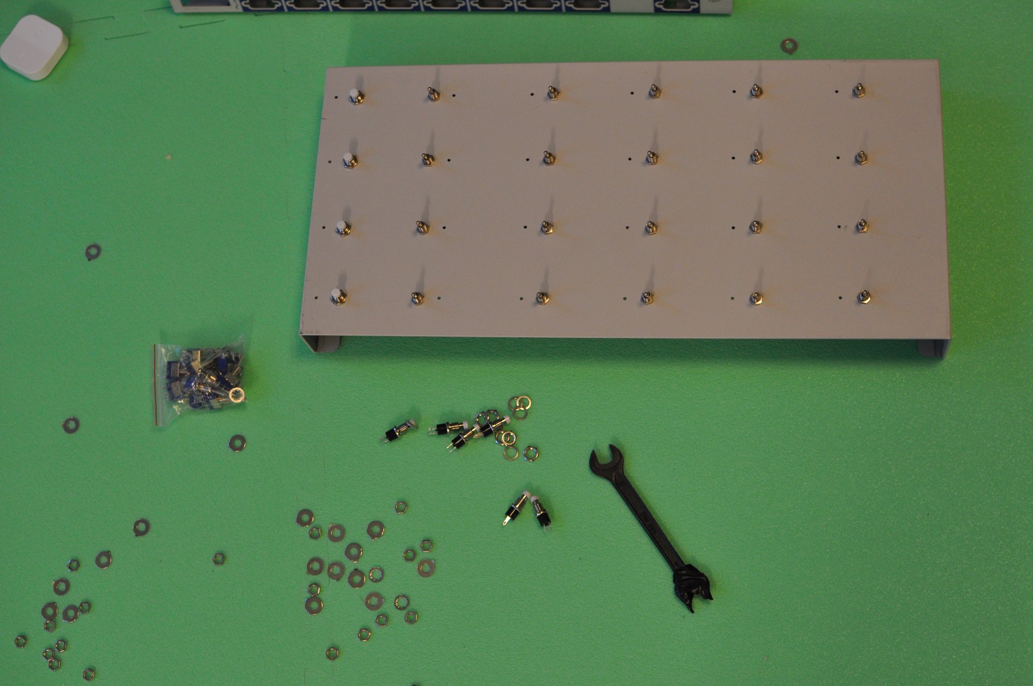 All switches mounted
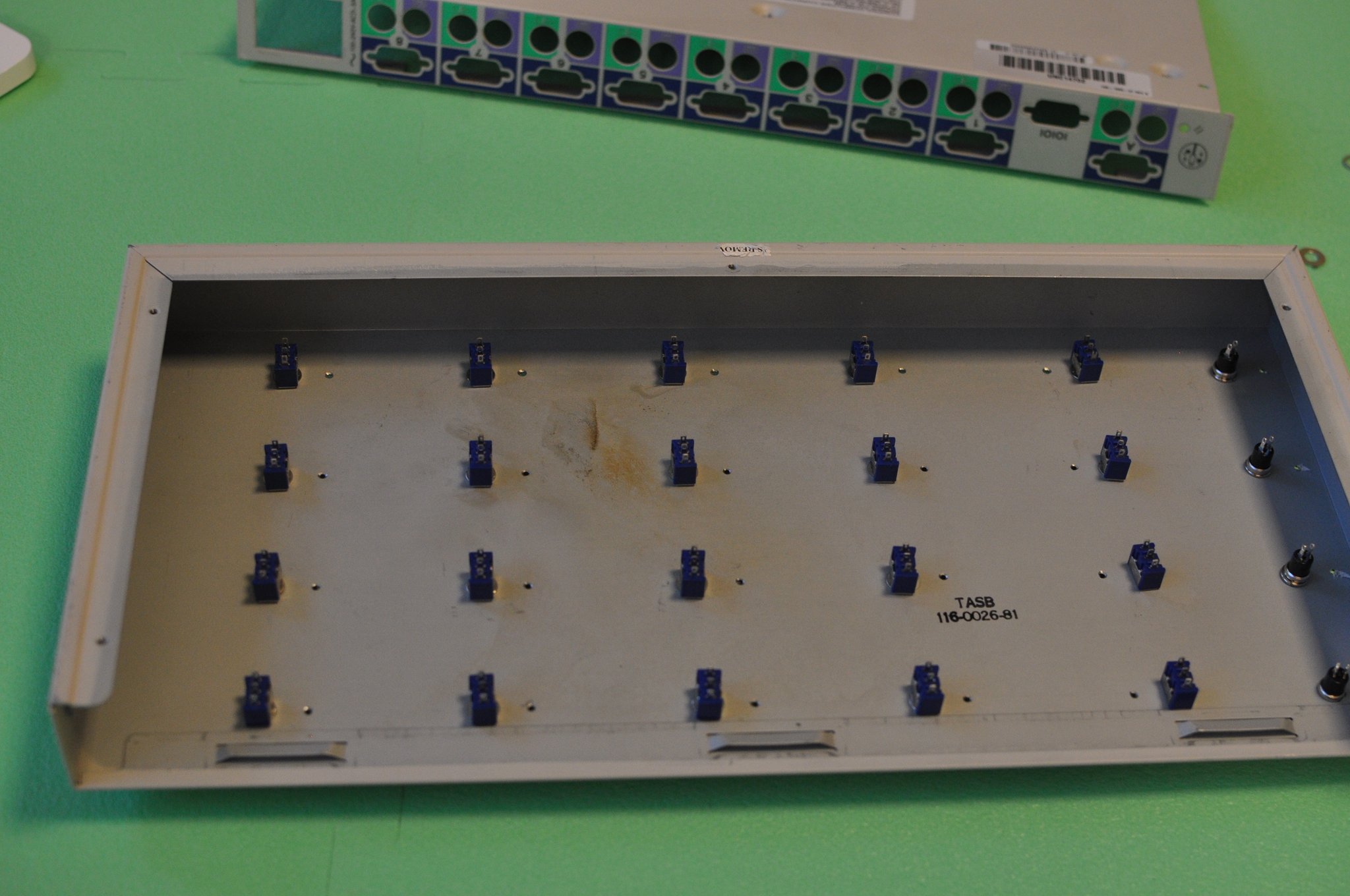 Interior side of the panel
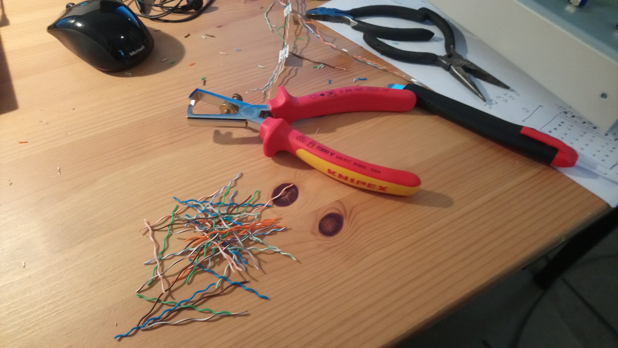
2020-10-12: First I will solder the indicator lights. They will be made of WS2815 LED strip. After cutting the strip into individual LEDs I prepared wires for connection. I used individual strands from FTP ethernet cable - not the best choice by far. I measured required lengths and cut the wires into segments, then stripped the insulation of the ends of the wires.
I heated up the soldering iron - it's time to burn some plastic. First I made 4-LED segments then I connected them by slightly longer wires. Each LED has 3 incoming wires (VCC, GND, Data In) and 3 outgoing wires (VCC, GND, Data Out). The LEDs are driven in shift-register fashion. After 2 hours of soldering, multiple fingers burns and few cursing sessions all wires were in place.
That was time to swap one hot tool - the soldering iron for another - hot glue gun. First I filled the indicator light holes with hot glue and prepared a little hot glue patches where the LEDs will be glued in. Hopefully the glue will act as a light guide. Then I glued in individual LEDs, bending the wires into positions. Luckily enough I did not break any of the wires. The hot glue leaves web of thin, sticky, tangling plastic fibers all over the place, so I needed to remove them first.
Test time! First I tested the connections with a multimeter to see if there are any shorts. Surprisingly there were not. Then I hooked up an ESP8266 MCU with WS2815 LED test program loaded to the LED chain. At first, it did not work. I discovered the ESP8266 dev board used does not output 5V on the pin header as previous version of the board did, So I hooked up additional USB break-out to get the power going to the LEDs. It worked miraculously.
 Wire stripping
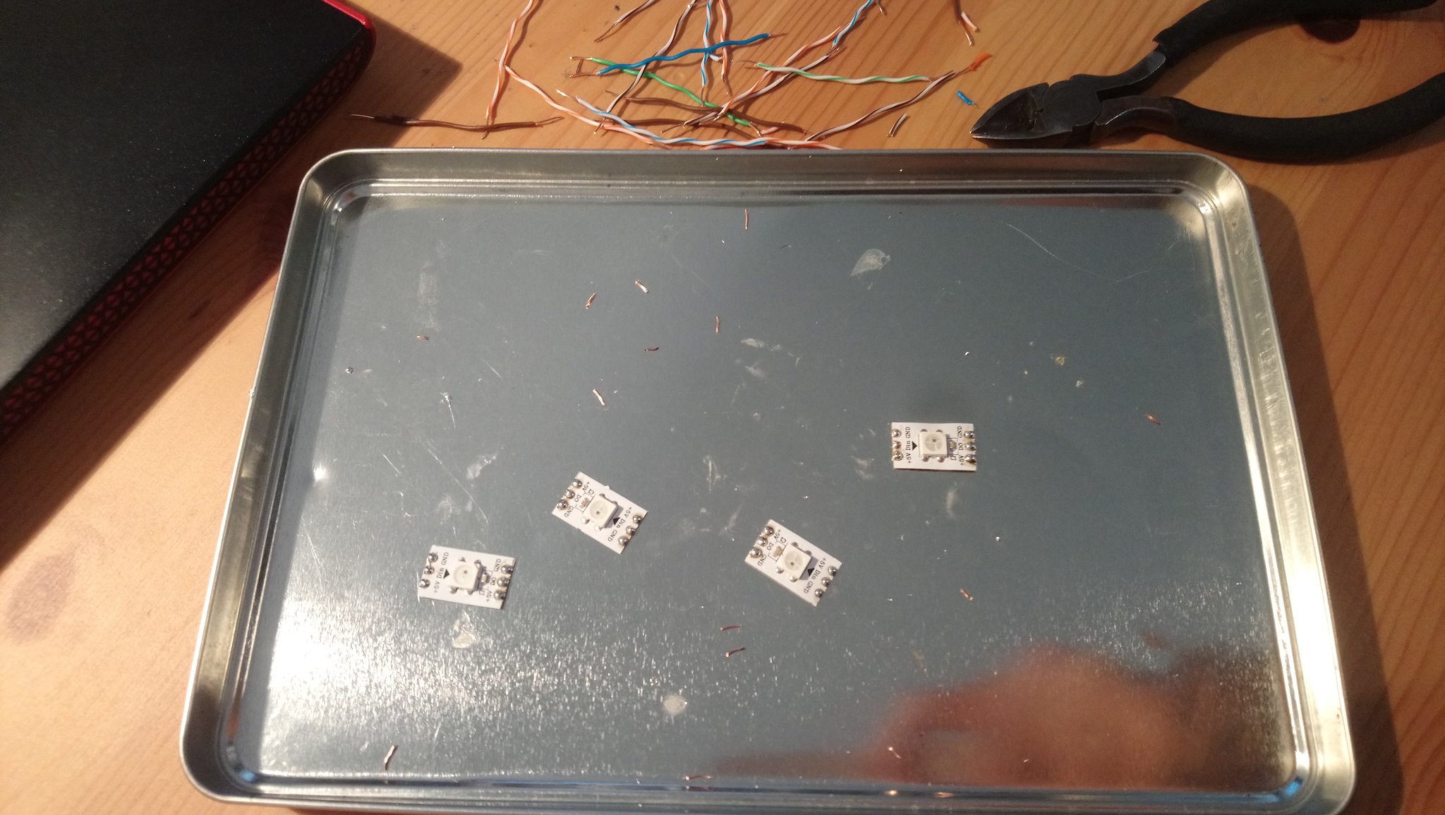 LEDs from LED strip
 Soldering
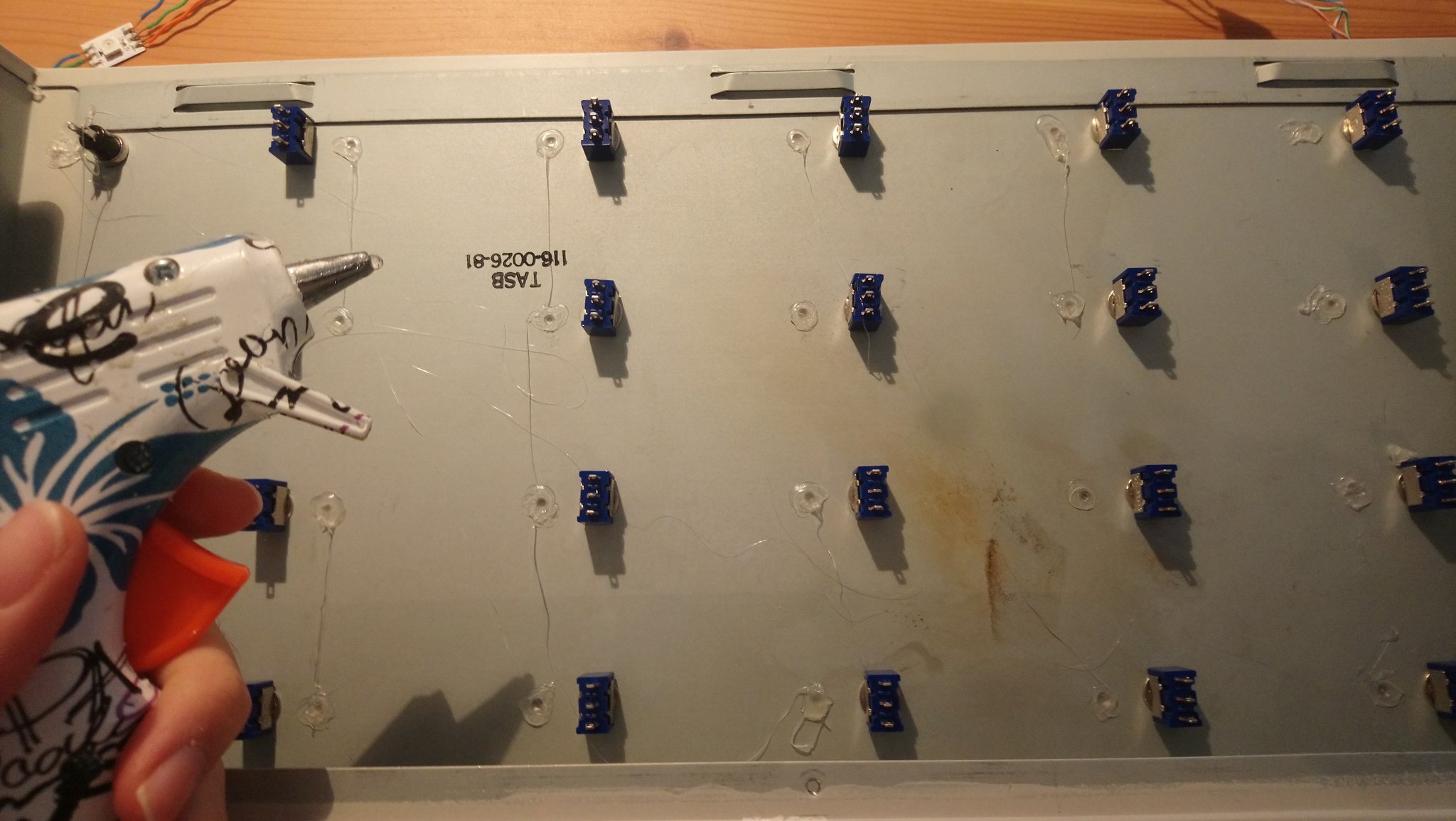 Hot glue spots
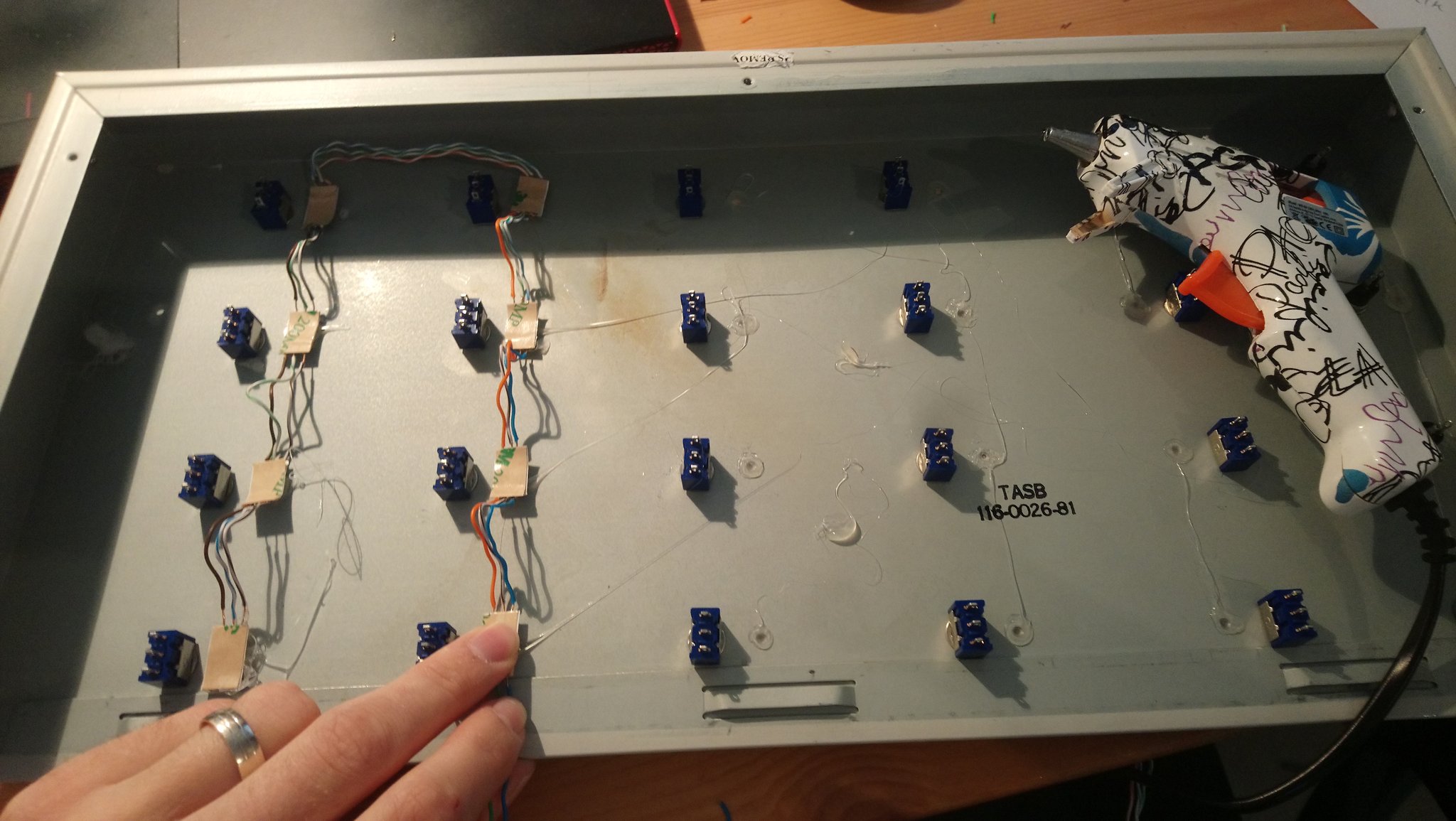 Glueing of the LEDs
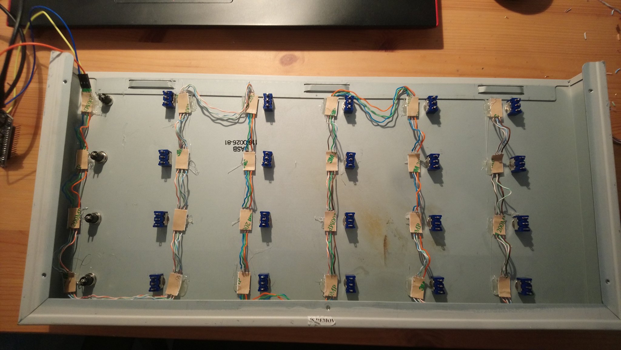 All LEDs in place
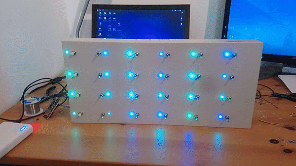 LED test
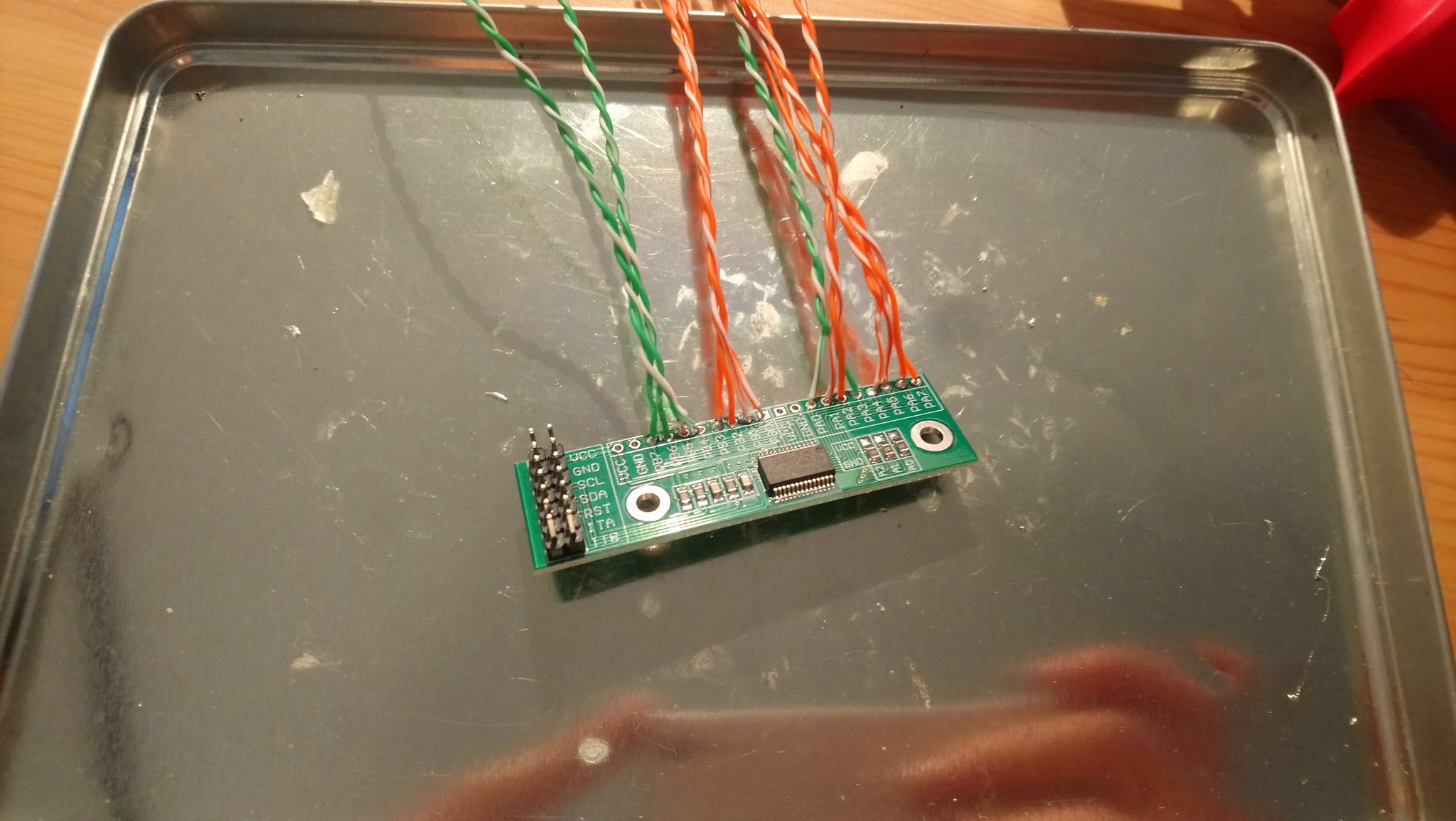
2020-10-13: After having LEDs in place, I connected the switches. First I connected the common contact for the switches by one long wire in a zig-zag pattern between rows. Then I measured necessary lengths of individual wires from each switch to IO boards. I soldered pin headers and wires on the IO boards first, then weaved the wires between existing wiring and soldered on the switch side. I did not bother to strip the insulation, I shrunk enough with heat applied to be able to firmly solder the end of wire. Even when I have thought the switch-wire order through, I changed the wire routing midway during soldering so I will need to remap the switches in software. The switches are all grounded and connect the pull-up input of the IO board to ground when active. IO boards contain one MCP23017 I2C IO extender each, two boards providing 32 I/O ports total.
 IO board soldering
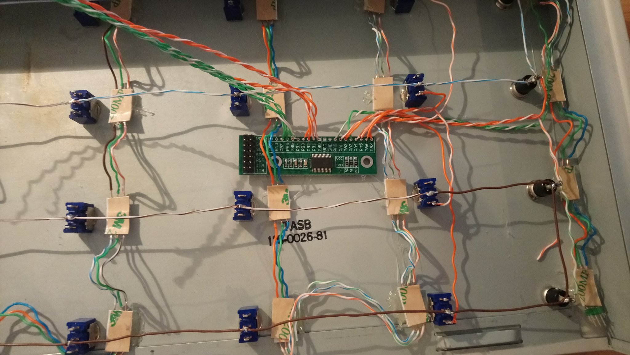 IO board in place
2020-10-14: The IO boards are in place & wired, so It's time to hook up the ESP8266 again and test the switch inputs. First I struggled with setting up the MCP23017 control library (it accepted address offset of manufacturer specified base address instead of whole address as I presumed). But then, the switches started to work. I added MQTT library and coded the logic for sending switch events to MQTT broker.
 Testing the IO boards
2020-10-15: Today I coded LED control logic for ESP8266 and started coding computer-side daemon to execute the switch-controlled actions and report the status back to the panel.
2020-10-17: The daemon is nearly finished, most time took fiddling with right commands
for required actions. The daemon is written in TypeScript, run in NodeJs as a SystemD User service. It listens for
switch events and can execute actions by interfacing with NetworkManager (VPN connection control),
PulseAudio (audio source selection) and run arbitrary commands (for remote filesystem mounting and starting applications).
It reports status back to the control panel: Green is running, red is stopped.
2020-10-18: Did some more tweaking of the daemon, added Orange state
to show if the current state does not match the selected state.
 Switch labels
BOM
  1x metal case
 20x lever switch
  4x push button switch
 24x WS2815 LED
  2x MCP23017 with breakout board
  1x NodeMCU (ESP8266)
Final result
Source code repository: https://github.com/janci007/control-panel/