Menu
Dual thermometer
In progress, last update 2022-04-28In failed seek of a good medical thermometer I decided to build my own. I wanted to replace:
- Cheap IR thermometer, acting like random number generator
- Super-slow gallium medical thermometer
- Super-fast digital medical thermometer (beep-beep type). It beeps after few seconds, uselessly reporting 34.5°C body temperature or so
I found this nice TSIC 506F on Farnell with 0.1 °C accuracy. Also I had one infrared thermometer module in the drawer. I decided to make a dual thermometer, with precision contact probe and less accurate IR probe.
BOM
1x TSIC 506F contact thermometer
1x MLX90614 infrared thermometer
1x ATmega328P board (Arduino Nano compatible)
1x OLED display module
1x button
1x switch
1x 5V DC-DC step-up
Schematic
TBDSoftware
The thermometer has 3 operating modes: dual mode, IR mode and contact mode. The modes are switched by single button, starting with dual mode.In dual mode, two temperatures are displayed one below the other. In IR mode, the IR probe temperature and current emissivity settings is shown. By long-perssing the button, emissivity constant can be changed. In concat mode, current and maximum* temperature of the contact probe is shown. By long-pressing the button, maximum reading can be reset.*
* Yet to be implemented
Enclosure
To house the electronic, I designed a simple box in FreeCAD. It was my second FreeCAD design ever, so I struggled with it greatly. The large size of the box is mainly due to using AA batteries as a power source and my desire to have the OLED display on the front face. I might do a v2 with better organization for a smaller device.I started by sketching the box bottom. I padded the sketch to make bottom wall of the box and then added sketches on each side-face of the bottom wall. I sketched the wall contours with openings for OLED display and USB port. I padded the skethes to make side walls of the box. Finally I added a datum plane on the top of the box and translated it downwards to make a positon for screw holes. There I sketched a 90° section of a circle with a hole inside for the screw.
I imported battery holder STL file and added cover plate. I used a shape binder to transfer the screw hole position to the cover plate. Then I used the Hole function to create countersunk holes in the cover for screwing it to the box body.
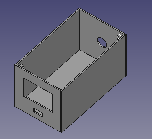 Enclosure
 Cover with battery holder
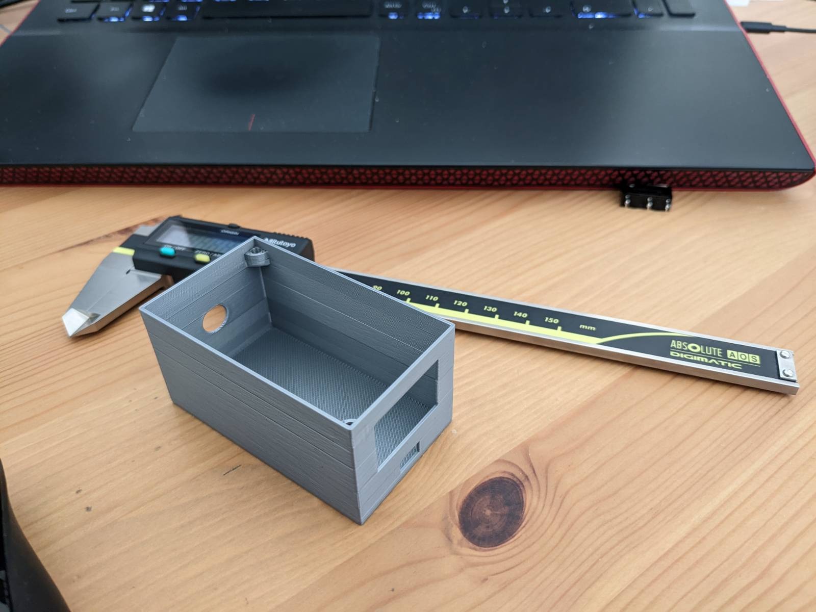 3D printed box body